Deploying a robust multi-display workstation architecture across a heterogeneous hardware fleet requires a strict evaluation of physical layer protocols, bandwidth allocation, and hardware-level compatibility. IT administrators and systems engineers frequently encounter deployment failures when treating a docking station simply as a passive port replicator. At the hardware level, these devices function as complex signal multiplexers, negotiating PCIe lane routing, DisplayPort video streams, and standard USB data packet transmission simultaneously.
The physical connector form factor—specifically the widespread adoption of the USB Type-C interface—obscures the underlying protocol variations programmed into OEM motherboards. A Type-C port on a host machine may support data only, data and power, or data, power, and video. Attempting to standardize an entire enterprise fleet on a single docking architecture without analyzing the host-side Graphics Processing Unit (GPU) capabilities and physical pin mappings inevitably leads to display enumeration failures, reduced refresh rates, or driver kernel panics. Designing a reliable multi monitor docking station environment dictates an engineering-level understanding of how video signals are generated, compressed, and transported across different hardware architectures.
Why Multi-Display Workstations Require Advanced Docking Solutions
Modern enterprise workstations require immense throughput to simultaneously handle multiple high-resolution displays, gigabit network traffic, high-speed peripheral data storage, and host charging via Power Delivery (PD) negotiation. The challenge lies in the physical constraints of the host interface. The USB-C connector consists of 24 pins, including four high-speed SuperSpeed differential pairs (TX/RX) utilized for high-bandwidth data transmission.
When a device connects to an enterprise docking station, the host controller and the dock's internal bridge chipset execute a complex handshake to determine how these differential pairs are allocated. If the workstation demands dual 4K external displays, the total bandwidth requirement often exceeds the native capacity of a standard USB 3.2 Gen 2 bus. Consequently, advanced docking architectures employ specific hardware or software methodologies—such as Alternate Mode pin reassignment, protocol tunneling, or software-based frame compression—to bypass these physical layer limitations.

System architects must factor in the varying implementation of the Type-C specification by different PC manufacturers. A configuration that successfully drives three displays on an Intel-based chassis might fail entirely on an ARM-based architecture due to differing internal bus topologies. Understanding the differences in these data transport mechanisms is the baseline for specifying hardware that will function deterministically across diverse laptop models and operating systems.
Understanding the Major Docking Technologies
Enterprise IT architects must differentiate between hardware-driven native GPU passthrough and software-driven virtual graphics rendering. The three primary architectures deployed in modern enterprise networks each utilize distinct data link routing logic. Evaluating these technologies requires looking beyond marketing specifications and analyzing the actual controller ICs utilized on the PCBA.
USB-C Alt Mode
USB-C DisplayPort Alternate Mode (Alt Mode) operates by physically reconfiguring the high-speed differential pairs within the Type-C cable to carry native DisplayPort (DP) signaling directly from the host system's GPU. In this architecture, the usb c docking station functions primarily as an active signal splitter and protocol converter, relaying the uncompressed video stream to the external monitors without significant latency.
To support multiple displays via a single Alt Mode connection, the architecture relies on Multi-Stream Transport (MST) technology. An MST hub integrated into the dock receives a single, high-bandwidth DP stream and hardware-demultiplexes it into separate, independent video streams for each connected monitor. The critical limitation of MST architecture is its strict reliance on host GPU capabilities and operating system support. Notably, the macOS WindowServer architecture does not natively support MST for extended display outputs, resulting in mirrored displays when connected to an MST-dependent dock.
Furthermore, overall resolution and refresh rates are bottlenecked by the host port's specific High Bit Rate (HBR) classification (e.g., HBR2 vs. HBR3). If a host system only supports HBR2, the available bandwidth is severely restricted, regardless of the dock's internal capabilities. For a comprehensive breakdown of pin allocations and DP handshake states, review our engineering documentation detailing why USB-C ports don’t all support the same number of displays.
Thunderbolt Docking Technology
Thunderbolt technology (versions 3, 4, and the emerging Thunderbolt 5 standard) abandons the dedicated pin-reassignment approach of standard Alt Mode in favor of protocol tunneling. The host system's Thunderbolt controller aggregates separate native data streams—PCIe, DisplayPort, and standard USB—and time-division multiplexes them into a single, unified micro-architecture stream.
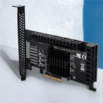
When this tunneled data reaches a thunderbolt docking station, the dock's internal controller (such as an Intel Goshen Ridge or Titan Ridge chipset) demultiplexes the stream back into its constituent protocols. Because Thunderbolt architectures operate with significant bandwidth reserves (Thunderbolt 4 mandates support for dual 4K displays by enforcing strict bandwidth minimums for video tunneling), they provide the lowest latency and highest uncompressed graphical fidelity available for multi-display setups. This makes native Thunderbolt architectures optimal for workstations executing complex CAD renders, financial modeling, or intensive video processing pipelines.
However, hardware compatibility remains rigid; the host machine must feature a discrete Thunderbolt controller chip to establish the high-speed link. For standardized environments demanding maximum throughput and dual-display capability via native GPU output, deploying a comprehensive solution like the PURPLELEC 19-in-1 40Gbps Thunderbolt 4 Docking Station provides the necessary 40Gbps architecture. For engineering departments requiring expanded peripheral matrices alongside high-end display topologies, hardware such as the PURPLELEC 20-in-1 Thunderbolt Docking Station ensures adequate internal bridge bandwidth for sustained data payloads while managing complex thermal dissipation requirements.
DisplayLink Graphics Technology
DisplayLink completely diverges from native hardware GPU passthrough. Instead, it utilizes a CPU-bound, software-virtualized rendering pipeline. The host machine runs a kernel-level virtual GPU driver that intercepts display framebuffers from the operating system. Utilizing proprietary, adaptive real-time compression algorithms, the driver encodes these video frames and transmits them as standard USB Bulk data packets over a conventional USB data bus.
Upon reaching the dock, a dedicated Application-Specific Integrated Circuit (ASIC)—such as the Synaptics DL-6950 SoC—decodes the compressed data, reconstructs the pixel data, and outputs the standard video signal (HDMI or DisplayPort) to the monitors. Because this process treats video as standard data payload, it inherently bypasses the hardware limitations of the host system's physical video output pins.
This enables up to four or five external displays from a single standard USB connection, agnostic of the host's innate GPU display pipeline limits. This software-driven approach standardizes behavior across Windows, macOS (including Apple Silicon M-series chips), and ChromeOS. It is highly resilient to mixed-hardware environments. To inspect the specific frame buffering and CPU overhead metrics of this technology, refer to the technical specifications on how DisplayLink works.
Bandwidth Limitations and Display Topology
The primary engineering constraint in multi-monitor workstation design is bus bandwidth. An uncompressed 4K display operating at 60Hz requires approximately 12.5 Gbps of sustained throughput. Connecting two such displays requires 25 Gbps, leaving very little overhead on a standard 40 Gbps Thunderbolt connection for external PCIe NVMe storage or Gigabit Ethernet.
In USB-C Alt Mode topologies, the bandwidth math is even more restrictive. A standard USB-C port operating over USB 3.2 Gen 2 provides only 10 Gbps of total data throughput. When Alt Mode engages to transmit video, it reallocates either two or all four of the high-speed differential pin pairs. Reallocating all four pairs to DisplayPort allows for maximum video resolution (e.g., dual 4K at 30Hz or single 4K at 60Hz) but downgrades the remaining USB data pins to legacy USB 2.0 speeds (480 Mbps), severely bottlenecking modern peripherals and external storage.
To mitigate these physical layer restrictions, modern dock architectures implement Display Stream Compression (DSC) 1.2a. If both the host GPU and the dock's internal chipset support DSC, the video stream is visually losslessly compressed, drastically reducing the required throughput and freeing up differential pairs for SuperSpeed USB data. When engineering a multi-display topology, the IT architect must calculate the total combined bandwidth of the required display resolutions, refresh rates, and anticipated peripheral data loads to select the appropriate underlying protocol.
Docking Stations in Enterprise Deployment
Scaling docking hardware across an enterprise introduces complexities absent in single-user setups. OEM (Original Equipment Manufacturer) docks are typically engineered with firmware dependencies tied directly to the motherboard BIOS of their respective proprietary laptop lines. While this ensures deep integration (such as MAC Address Passthrough for PXE booting and Out-of-Band management) when deployed uniformly, it causes critical failures in mixed fleets. Connecting a non-OEM device to an OEM dock frequently results in reduced power delivery negotiation, disabled MST hubs, or unrecognized peripheral interfaces.
Universal docking architectures prioritize cross-vendor predictability. By relying on standardized protocol layers—such as universal USB Power Delivery (PD 3.0/3.1) handshakes and OS-agnostic DisplayLink rendering—these deployments maintain deterministic behavior regardless of the connected host. A properly engineered universal dock contains programmable PD controllers that can dynamically negotiate voltage and amperage contracts (e.g., 20V/5A for 100W delivery) without requiring proprietary host-side communication. This reduces Help Desk ticket volume related to display connectivity issues and battery drain under heavy CPU load.
Choosing the Right Docking Architecture for Mixed Device Environments
Selecting the appropriate physical layer technology requires matching the dock's internal routing capabilities to the end user's specific computing payload. Procurement decisions based solely on physical port counts inevitably lead to localized deployment failures.
For workloads dominated by highly parallelized GPU computations—such as 3D modeling, real-time video rendering, and intensive localized data processing—native hardware passthrough is non-negotiable. Thunderbolt architectures provide the uncompressed, low-latency PCIe and DP tunnels required. Utilizing a DisplayLink dock in a CAD environment would introduce unacceptable rendering latency and CPU overhead.
Conversely, for heavy multitasking operations, financial analytics arrays, and general corporate productivity where screen real estate is prioritized over localized GPU rendering power, software-virtualized docks provide unmatched scalability. They reliably drive multiple high-resolution panels regardless of whether the user connects an Intel-based Windows machine or an Apple Silicon MacBook.
Understanding these divergent hardware requirements is essential for designing standardized IT profiles. For detailed matrices mapping user personas to specific hardware topologies, consult our systems engineering guide on Choosing the Right Dock for Mixed Environments.
IT Deployment and Management Considerations
Integrating complex docking topologies into the enterprise network requires robust lifecycle management strategies. The underlying technology heavily influences OS imaging, driver distribution, and endpoint security policies.
Thunderbolt and standard USB-C Alt Mode setups generally rely on natively integrated OS drivers, simplifying zero-touch deployment via systems like Microsoft Endpoint Configuration Manager (MECM) or Intune. However, firmware updates for the dock's internal MST hubs and PD controllers often require localized administration or specific vendor utilities to flash the onboard EEPROM.
DisplayLink deployments necessitate the distribution and management of the DisplayLink Manager application or specific kernel extension drivers. IT administrators must package these drivers into their standard corporate OS images and manage security permissions—specifically Screen Recording permissions required by macOS for virtual GPU rendering—via Mobile Device Management (MDM) configuration profiles to prevent user friction during the initial hardware setup.
Power mapping is an equally critical deployment factor. The dock must contain a Power Delivery controller capable of negotiating the precise voltage and amperage required by the highest-demanding laptop in the fleet, typically ranging from 65W to 100W, to ensure sustained CPU performance without battery degradation. For comprehensive integration strategies, network access control configurations, and bulk deployment blueprints, review our documentation on How to Deploy Docking Stations for Enterprise. For further technical briefs and architecture breakdowns, access the PURPLELEC Blog.
Conclusion
The structural integrity of an enterprise multi-display fleet relies entirely on correctly aligning the host machine's hardware capabilities with the docking station's internal signal processing architecture. Physical interface similarities mask critical disparities in underlying protocol support, bandwidth limitations, and rendering logic.
Network engineers and IT architects must transition away from port-matching procurement strategies and evaluate docking hardware based on its core routing technologies. Deploying Thunderbolt for high-bandwidth, latency-sensitive local rendering, USB-C Alt Mode for baseline native displays, and software-based virtual architectures for expansive, cross-platform monitor arrays ensures systemic stability. Analyzing the internal topology of these devices guarantees that the physical layer will successfully support the organization's evolving compute requirements.
For direct engineering support regarding mixed fleet compatibility matrices, PD negotiation troubleshooting, or advanced configuration inquiries, contact our hardware integration specialists at the PURPLELEC technical desk via contact@purplelec.com.